Engine Rebuild Stand
Posted: Fri Apr 03, 2020 12:28 am
With some extra time over the last couple weeks to spend in the workshop, I decided it would be a good opportunity to tackle some projects I had on the long term list. The first of which was a new engine stand, which would be attempt number three for me, and I had decided I would only do it if I could end up with something really nice. Attempt number one had been similar to any generic cheap stand, number two had some stronger tubing, flange bearings for the pivot and incorporated a worm gear set in a box I made out of some steel plate. This had good potential, but ultimately the worm gear would have needed some more work, and the whole thing couldn't really handle a really heavy load.
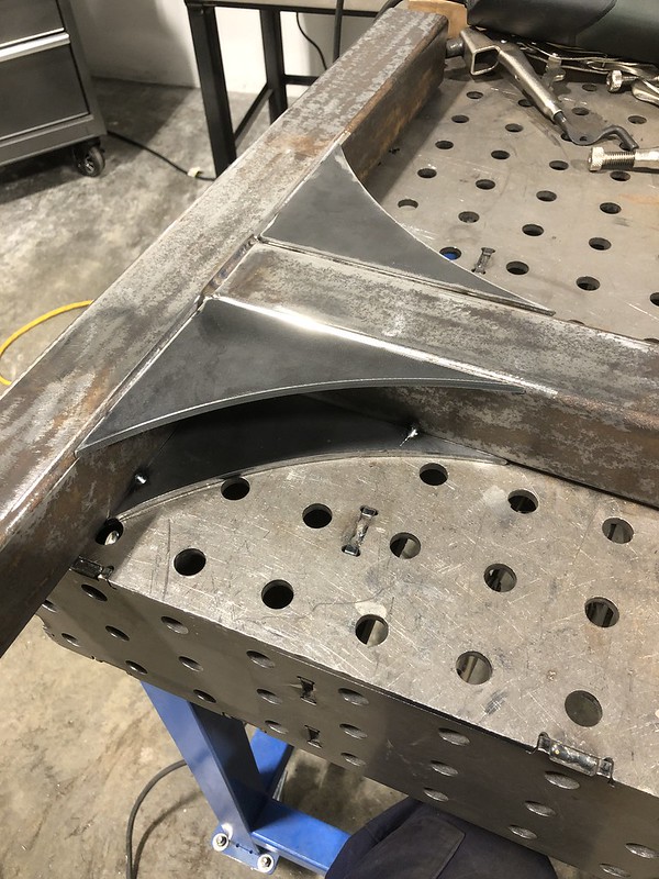
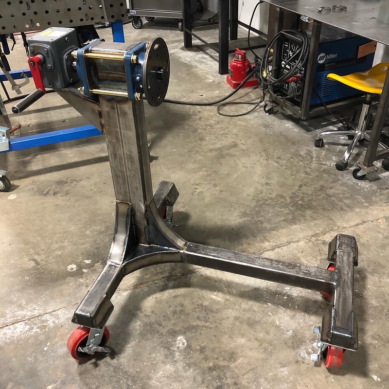
I've been acquiring some of the components for this for a couple years in anticipation of someday having some time... So, it started out with some much heavier duty steel box tubing. 2.5x2.5x3/16" for the base, and 3x5x.25" for the vertical member. I had internally dubbed this project "engine stand HD". I wanted to avoid any tall gusseting that might clutter the work area up around the engine, and I needed to provide a wider base for the vertical member to sit on to make up for the extra .5" width of the tube, so I cut out 10 matching curved gussets from some 3/16" plate to weld in the corners, and then covered those in some lighter gauge strips to box it all in. Prior to welding the vertical tube in I spent some time getting it well clamped to try and keep it square while welding.
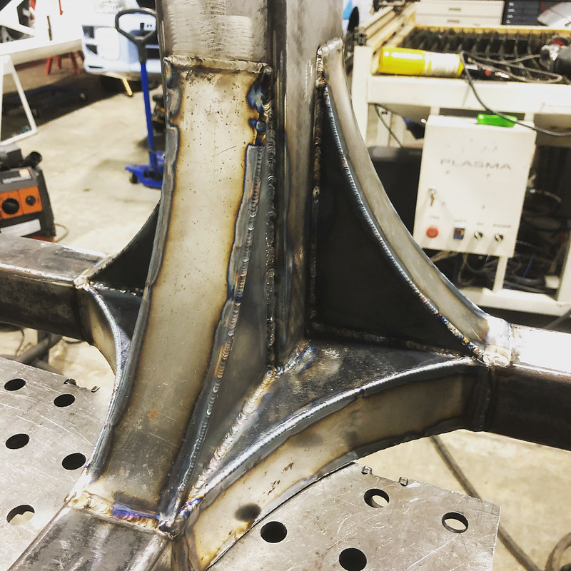
After that I made some plates to bolt some locking castors I already had to the stand. These got some weld nuts on the plates and 14ga gussets, more to clean up the look then actually add strength as I don't think that would have been necessary.

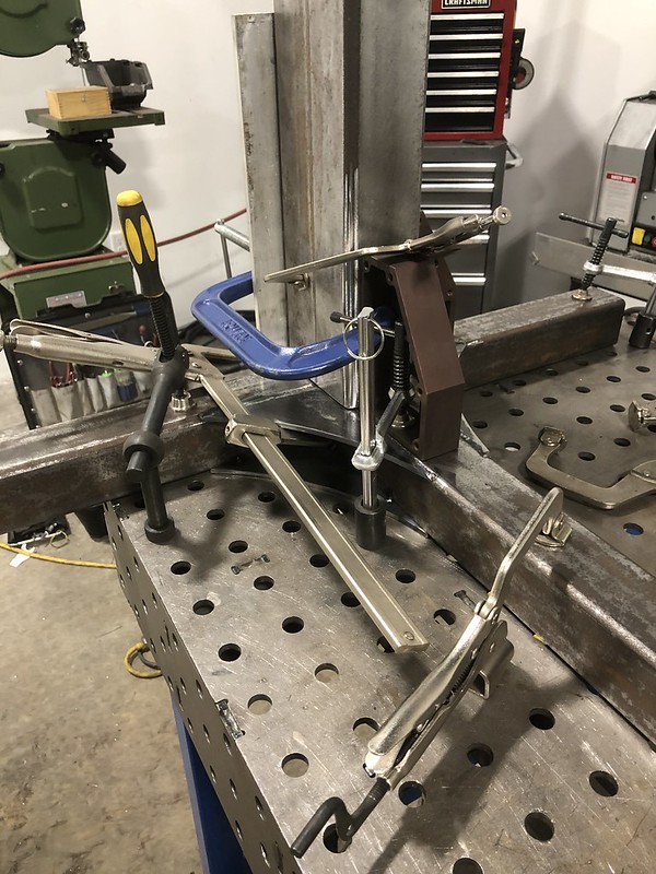
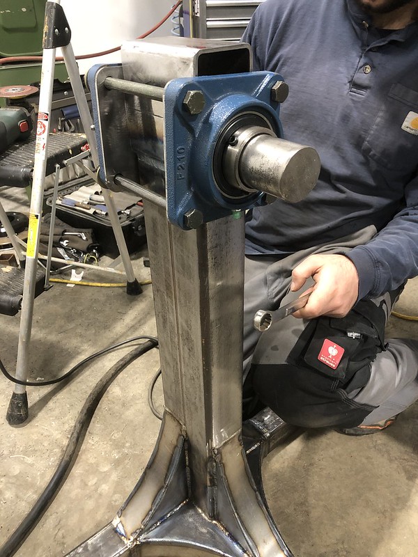
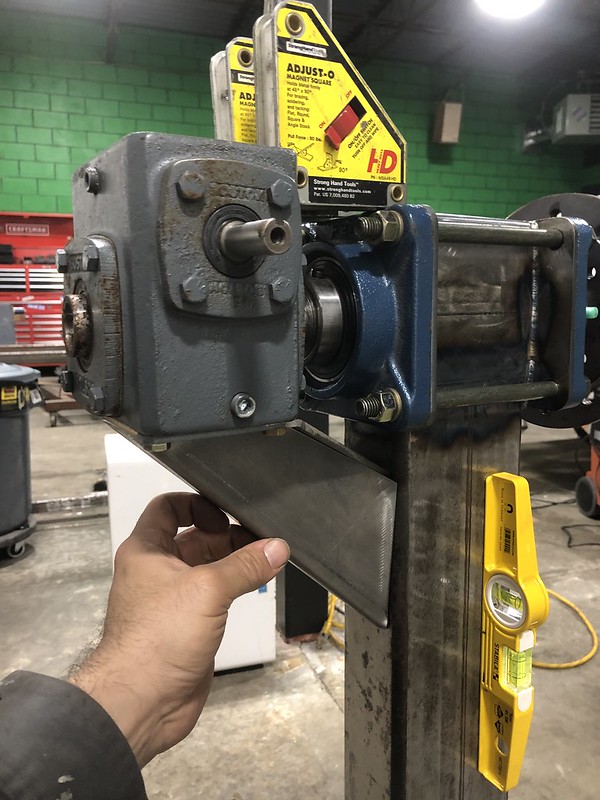
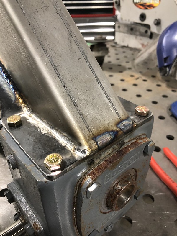
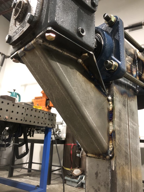
Next up was to get the head of the stand welded on, with mounting plates for the flange bearings that will carry the rotating shaft and faceplate. The flange bearings and 2" shaft were used to keep everything lined up during welding.
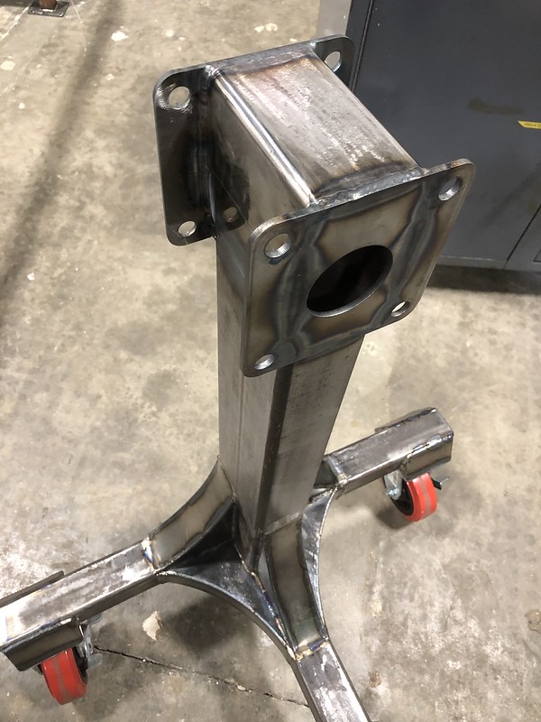
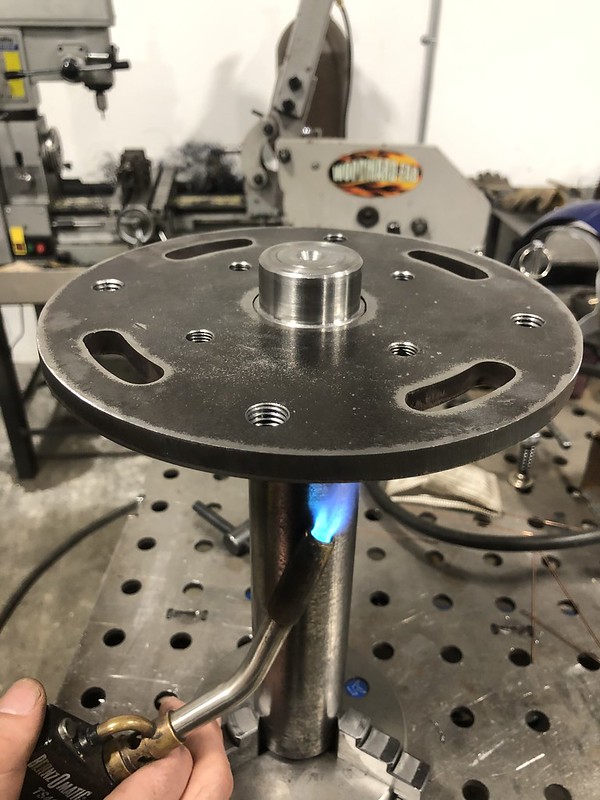
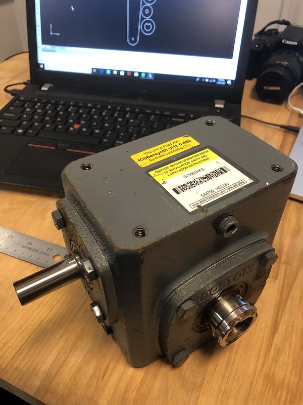
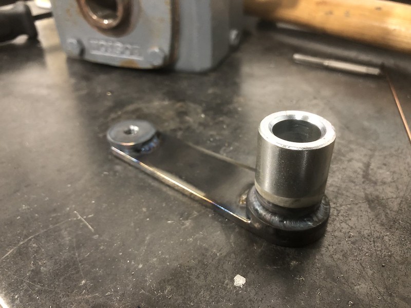
After that was done the shaft was removed and both ends were turned down. One side needed to step down to 1" to fit into the worm drive assembly Im using, and for the front I added two steps. The first gave me a shoulder to press the faceplate down onto and a good place to weld it on the front while maintaining a nice flat mounting surface for the fixtures. The second step down is intended so any fixtures can incorporate a common size tube where the ID would fit onto the short stub to help take some of the weight and make it easier to line things up. I also cut out a faceplate from a piece of 3/8" wear plate I had bought at a local steel yard from the buy the pound section. It had a center bore that would press onto the shaft, and a selection of threaded holes and slots for fixing options for various fixtures. In the photo its being preheated before welding the front and back to the shaft.
I've been acquiring some of the components for this for a couple years in anticipation of someday having some time... So, it started out with some much heavier duty steel box tubing. 2.5x2.5x3/16" for the base, and 3x5x.25" for the vertical member. I had internally dubbed this project "engine stand HD". I wanted to avoid any tall gusseting that might clutter the work area up around the engine, and I needed to provide a wider base for the vertical member to sit on to make up for the extra .5" width of the tube, so I cut out 10 matching curved gussets from some 3/16" plate to weld in the corners, and then covered those in some lighter gauge strips to box it all in. Prior to welding the vertical tube in I spent some time getting it well clamped to try and keep it square while welding.
After that I made some plates to bolt some locking castors I already had to the stand. These got some weld nuts on the plates and 14ga gussets, more to clean up the look then actually add strength as I don't think that would have been necessary.
Next up was to get the head of the stand welded on, with mounting plates for the flange bearings that will carry the rotating shaft and faceplate. The flange bearings and 2" shaft were used to keep everything lined up during welding.
After that was done the shaft was removed and both ends were turned down. One side needed to step down to 1" to fit into the worm drive assembly Im using, and for the front I added two steps. The first gave me a shoulder to press the faceplate down onto and a good place to weld it on the front while maintaining a nice flat mounting surface for the fixtures. The second step down is intended so any fixtures can incorporate a common size tube where the ID would fit onto the short stub to help take some of the weight and make it easier to line things up. I also cut out a faceplate from a piece of 3/8" wear plate I had bought at a local steel yard from the buy the pound section. It had a center bore that would press onto the shaft, and a selection of threaded holes and slots for fixing options for various fixtures. In the photo its being preheated before welding the front and back to the shaft.


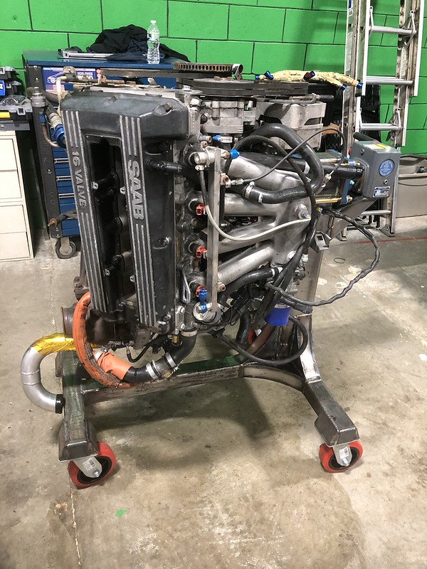
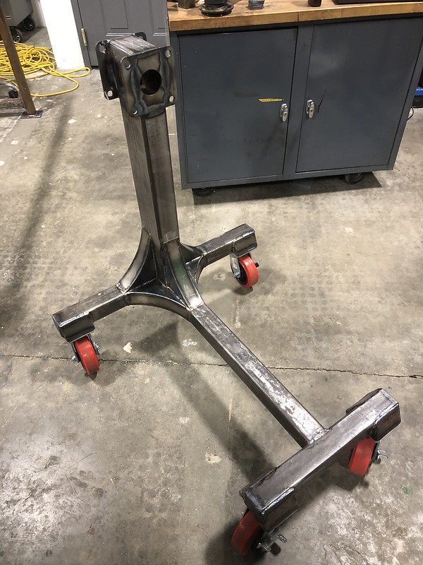
 I started off just cranking it back and forth smiling. Tomorrow Ill see how it goes unbolting the gearbox by myself and getting it off the block. Maybe I need an adapter for a jack or something.