Ok, warning, go grab a cup or tea or something to prepare for this one. It's longer than my other one.
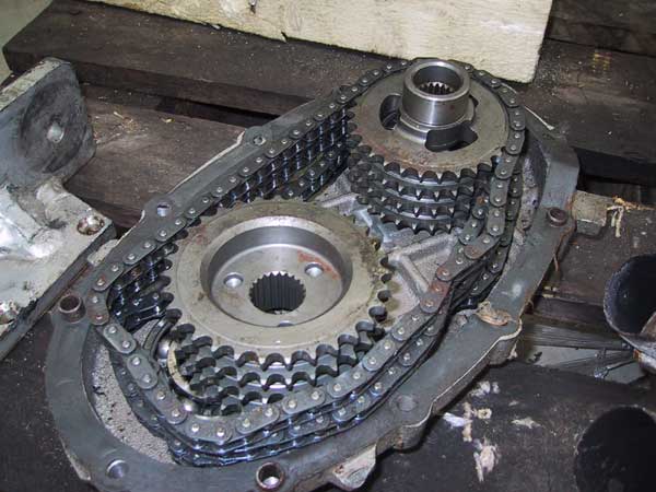
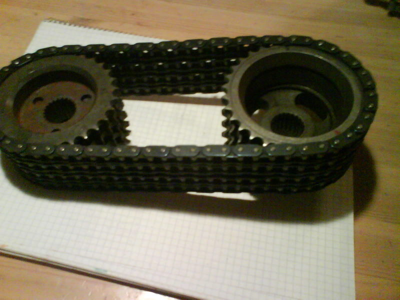
Luke wrote:FWIW, SAAB sport and rally 4 chain primaries did not use the staggered tooth design like the production gearboxes did. Presumably for ease of machining and because with the entire extra chain the strength was so much greater that the little bit of advantage the staggered teeth had was no longer neccessary.
Thanks Luke, I always get myself in trouble overthinking sometimes, the curse of the engineering degree. These wouldn't actually be too bad to make, the heat treat to keep the wear surfaces would probably be the hardest part, but some cut from 8620 round and a moderate through hardening would probably be fine, especially on dirt / gravel stages, tarmac might be a little bit much shock loading, it's hard to say. Neil, I don't know if you guys can broach the female spline drive or not, but I definitely don't have the tools to do that here, I single point cut some male splines into a 4340 stub, but it took
forever.
Crazyswede wrote:http://www.performance96.co.uk/Project_99/99Gearbox.html
That is fantastic, I hadn't seen it yet, thanks.
paulh wrote:Also, don't the 4 chain primaries have an extra bearing for the front of the top cog? I imagine this is the most important feature, as Delorean recently had the top cog on his trans break off the mounting nub in the trans. Seems like that extra bearing would take care of that form of failure.
I'd agree with that, it'd be a good preventative bit at least, and one could make the new outer bearing retainer integral to the little access cover to get the clutch shaft out pretty easily, especially if you made your own sprockets and could size the outer diameter.
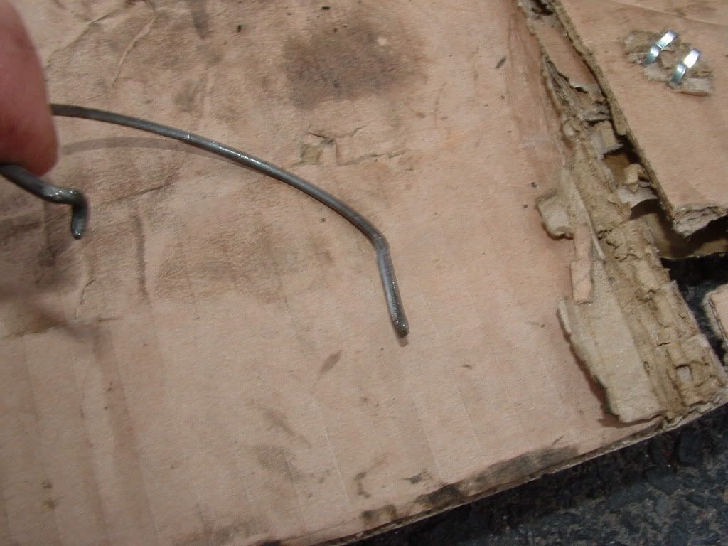
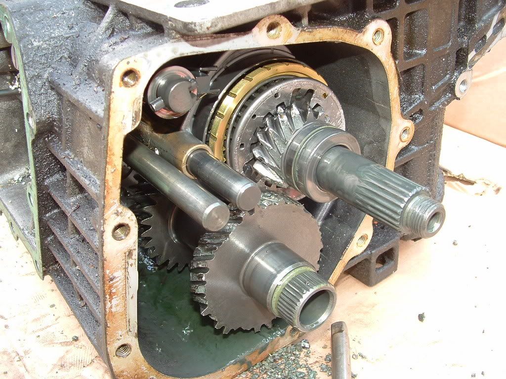
paulh wrote:One of the other oddball failures that seems pretty common is with the 91+ boxes, the synchro spring on 4th gear seems to occasionally just let loose, getting smashed in the gear cluster, causing a catastrophic gear failure.
Paul, I remember seeing photos of this last year or whatever, but isn't the syncro spring still in the 4th gear syncro in this photo? Did it come out of another gear?
I didn't even get to my coup de gras about the shafts flexing before.
So my theory goes that (in the case of the radial loads pushing the gears apart at least) the cases are pretty rigid, I mean, how can the mounting bores actually separate that much into the surrounding material, the bulkhead arangement like that is common, and works well for many many situations.
I believe that the flexing that can kill 2nd and 3rd is actually the splined output shaft flexing when loaded. I think it's the splined shaft and not the driving cluster because of how much smaller diameter the splined shaft is than the cluster. The cluster shaft is easily 20%-25% larger diameter, and flexural (bending) rigidity of shafts loaded like this goes up as the 4th power of diameter:
Bending moment 'M' = E*I, with E = modulus of material, I the area moment of inertia,
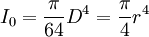
r = radius
D = diameter
So a 10% increase in diameter, from nominal size = 1, to size 1.1 is 1.1^4 = 1.46 times the bending stiffness of the original size 1 shaft, or a 46% increase in stiffness. That's why small increases in anti-roll bar diameter can have a drastic change in handling, torsional stiffness also goes up as the 4th power of diameter.
The cluster gear is (flexurally at least) much much more rigid than the output shaft, which has the driven gears all splined onto it (the splines are stress risers and weaken the shaft a little bit further).
The bad news is I still don't have a good way around this problem, what needs to happen is either to get a support on the upper-driver's-side of the output shaft to take the radial loading, like with a gusset into the upper corner of the case with a forked bearing support or something, or a 'dogbone' bearing carrier like some of the Honday transaxles can take, to tie the two shafts together from the center, but you'd have to re-space the output stack, and there's no way to get a bearing onto the cluster since the gears are cast on.
The last observation about gears - I don't know where the misconception on the internet came from that straight cut gears are stronger than helical gears, but I can remember consistently seeing this for as long as I can remember reading about upgrading the transmission.
Helical cut gears are
stronger for a given width and diameter, i.e. it takes more torque to rupture the teeth. Helical gears require larger and different bearings for the same size gears though because of the additional radial and thrust loading, so it's a packaging compromise
Straight cut gears don't have wider teeth. The tooth geometry can be made almost identical between the two cut types for equivalent sized gears, and the teeth can be just as wide, but the helical gear's advantage is two fold from a strength perspective:
1) The contact ratio, the number of teeth that are sumultaneously rolling across each other and transmissing load, can only be between 1.0 and 2.0 for straight cut gears. No more than two teeth can ever being transmitting load at once.Helical cut gears can have contact ratios greater than 2, depending on the width of the gear face, so the load can be spread across more of the gear face.
Contact ratio goes up as the width of the gear face increases, and as the helical angle increases (helical teeth wind more). The extreme is the worm gear, which has a very high helical angle, and can have many many teeth engaged sumultaneously depending on the geometry of the rack or gear being driven.

 How Gears Work, and Involute Profiles
Before part 2), check the bottom explanation of this link, about 'Involute Profiles.'
Notice that the faces of the teeth have a curved shape profile, and are not flat faces.
Involute profiles
Involute gearsThe curved involute faces appriximate a rolling motion as the gears turn and they roll across each other. The editor of the Wiki article
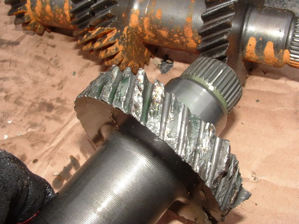
incorrectly states that involute gear faces slide along each other. The primary failure mode of involute profile gear teeth (other than rupture from overload) is pitting from micro-scale adhesion, not a sliding failure. The two modes look drastically different, and in the photo of the tooth faces in my gallery you can clearly see the pitting failure, not a sliding contact surface failure, which would have 'rub' lines sliding off the faces of the teeth.
 2) With straight cut gears the contact interface is called a line load, as the teeth mesh the contact point is a line along the width of the gear.
.jpg)
(technically, since the surfaces of the teeth deform as load is applied to load application is actually distributed in a rectangular profile, the harder the teeth push, the wider the rectangle).
If the shaft is short, stiff, and well supported from both ends, this is fine. If you're talking about the gears in a car trans mounted on a shaft, as the center of the shafts push apart from the radial load of the gears, the gear centerlines are no longer parallel.
The gears misalign, and the contact point goes from a nice line load to an uneven point load!!!
The misalignment and uneven tooth loading is worse for wider gears than narrower ones since smaller centerline misalignment angles can pull the ends of the teeth away from each other.
But with a helical gear, as above, the tooth contacts are closer to distributed point loads already, with the contact starting as the root of one tooth meets the crest of the mating tooth on the other gear, rolls up so both flanks are contacting, and then the tooth disengages as the crest of the first tooth rolls to the root of the mating tooth.
This happens simultaneously and continuously across multiple teeth as the gears mesh, depending on the helical angle.
So,
WHY STRAIGHT CUT GEARS??They can be cut. Helical gears are almost impossible to cut, and are almost exclusively hobbed, where a forming tool is forced into a smooth round blank and the teeth are literally pressed into the gear as the hobbing tool is rolled around the edge of the gear blank.
For low volume production like racing, getting the hobbing tools made is extremely costly (but makes better gears, residual compressive stress in the tooth surfaces strengthens the wear surfaces). Straight cut gears can be machined with a specially ground cutter which cuts the faces of two adjacent teeth by cutting out the root of the tooth. This way you can fairly inexpensively make many many different size gears to mate to a set of common splined shafts so you can change individual gear ratios, like for the Hewland series transmissions for open wheel cars, for example. Getting a hobbing tool made for each and every gear size and tooth count would cost literally millions.
The drawbacks of helical gears are the cost and complexity to manufacture, and the fact that the helical angle puts a thrust load in the direction of the shaft onto the gear, which both bends the shaft, and must be supported with a thrust bearing surface at one or both ends of the shaft to keep the shaft from sliding through it's bearings, thus part of the reason for the twin opposing tapered rollers in the pinion bearing housing, and the deep groove ball bearing at the front end of the case on the output shaft, and the single tapered roller at the back of the cluster gear.
I love engineering. But talk too much.
I swear I actually have a life too.
Best,
Drew