Re: T5 Wiring Harness Help
Posted: Fri Jan 20, 2012 3:19 pm
Function-------------------Black Plug(H33-4)--------------------------On Car
+30 Power-----------------Pin 5, White/Pink---------------------------Find your self any constant power.
+15 Power----------------Pin 21, Yellow/Gray Pin 23, Green/Gray----Again, find it yourself. I just used the coil circuit.
DI/AIC/Injectors +15-----Pin 2, Green/Red--------------------------Its up to you.
Main ECU relay------------Pin 12, Blue/Gray--------------------------Main ECU relay. I did NOT use the stock relays. Nor this lead.
Fuel Pump relay------------Pin 11, White------------------------------Fuel pump relay. Again I did NOT use the stock relays. Nor this lead.
O2 Pre-Heater-------------Pin 8, Yellow/Gray-------------------------This needs +15 switched power. I used the coil circuit.
Brake Light Switch----------Pin 25, Violet-----------------------------Run it over to the brake light switch. Since I think the only person who needs to know when I'm on the breaks should be behind me....I didn't hook it up.
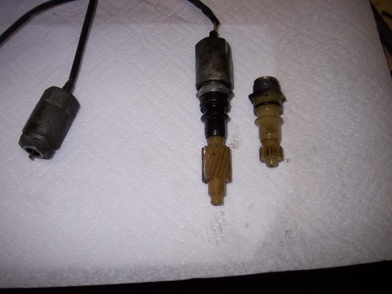
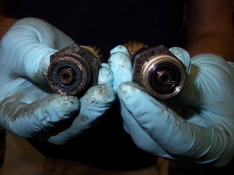
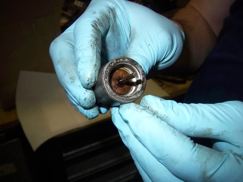
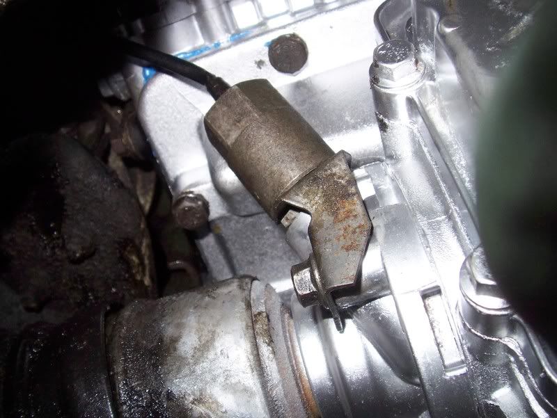
Speed Signal---------------Pin 7, Pink/Black(?)---------------------Above Jetronic Pin 1, Green (pic below)
Check Engine---------------Pin 22, Yellow/Green-------------------Above Jetronic Pin 4, Green/gray(?) (pic below)
Engine Speed(RPM)--------Pin 9 Green/Red------------------------Above Jetronic Pin 3, Blue (pic below)
Shift up--------Pin 22(H-33-5) Blue/Yellow------------------------Above Jetronic Pin 2 Yellow, Blue (pic below)
Grounds-------------------On end of T5 harness---------------------------Nice rust free spot.
^That came off Saablink, I found it to be a pretty helpful list when combined with a wiring diagram for the ng900 harness I used. The diagram was not for the correct year though, so like Drew said, some of the colors were different. But it didn't take too much to figure things out.
Because my car didn't retain the stock heater, I was able to put the ecu inside the cabin where the heater box would normally pass through the fire wall without extending the harness. As for the rest of the harness, I only needed to extend the wiring for the MAP sensor, intake air temp sensor and a few inches to the wiring for the AIC valve so that it could be routed nicely. I think it is definitely easier to use the existing T5 engine harness and just build something to adapt it to the car.
In MikeD's post he talks a lot about the big gray plug. If I was using a 9000 harness I think I would cut that out and add in something more compact like a deutsch connector, weatherpack etc. That big gray plug is just kind of bulky. The NG900 uses a smaller plug (the H33-4 referenced above) that I retained. Not sure what the plug type is called, but the are used all over in the ng900/9000, like whats used on the DI. Everything going to the car side of things runs through there, so it should make for a nice place to build an adapter harness off of, and thats what I did. The actual engine harness just needs to be unwrapped and then re wrapped to taste so that everything routes nicely around the engine. This is what I ended up with:
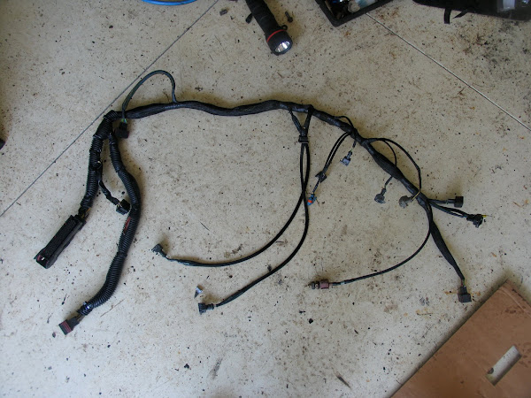
And this is what the car side I made looked like:
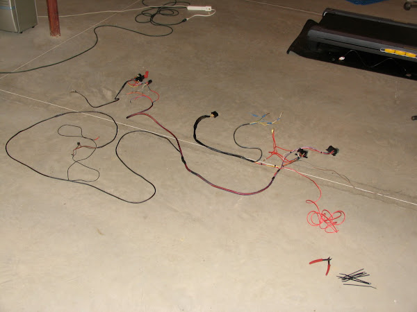
It includes the wiring that goes to the fuel pump, relays, plug that goes to the engine harness, and the wiring that goes to the gauge cluster.
Since I didn't retain any stock wiring in the car, I can't be of much help in terms of where to find things on the car side etc. I did use the stock main/fuel pump relays though. This is an area where some people have struggled and end up using other circuits. From what I found, I believe that the ECU will only ground the fuel pump relay if the main relay is triggered. So if you don't use the main relay ground from the T5 ecu, the fuel pump relay won't work.
+30 Power-----------------Pin 5, White/Pink---------------------------Find your self any constant power.
+15 Power----------------Pin 21, Yellow/Gray Pin 23, Green/Gray----Again, find it yourself. I just used the coil circuit.
DI/AIC/Injectors +15-----Pin 2, Green/Red--------------------------Its up to you.
Main ECU relay------------Pin 12, Blue/Gray--------------------------Main ECU relay. I did NOT use the stock relays. Nor this lead.
Fuel Pump relay------------Pin 11, White------------------------------Fuel pump relay. Again I did NOT use the stock relays. Nor this lead.
O2 Pre-Heater-------------Pin 8, Yellow/Gray-------------------------This needs +15 switched power. I used the coil circuit.
Brake Light Switch----------Pin 25, Violet-----------------------------Run it over to the brake light switch. Since I think the only person who needs to know when I'm on the breaks should be behind me....I didn't hook it up.
Speed Signal---------------Pin 7, Pink/Black(?)---------------------Above Jetronic Pin 1, Green (pic below)
Check Engine---------------Pin 22, Yellow/Green-------------------Above Jetronic Pin 4, Green/gray(?) (pic below)
Engine Speed(RPM)--------Pin 9 Green/Red------------------------Above Jetronic Pin 3, Blue (pic below)
Shift up--------Pin 22(H-33-5) Blue/Yellow------------------------Above Jetronic Pin 2 Yellow, Blue (pic below)
Grounds-------------------On end of T5 harness---------------------------Nice rust free spot.
^That came off Saablink, I found it to be a pretty helpful list when combined with a wiring diagram for the ng900 harness I used. The diagram was not for the correct year though, so like Drew said, some of the colors were different. But it didn't take too much to figure things out.
Because my car didn't retain the stock heater, I was able to put the ecu inside the cabin where the heater box would normally pass through the fire wall without extending the harness. As for the rest of the harness, I only needed to extend the wiring for the MAP sensor, intake air temp sensor and a few inches to the wiring for the AIC valve so that it could be routed nicely. I think it is definitely easier to use the existing T5 engine harness and just build something to adapt it to the car.
In MikeD's post he talks a lot about the big gray plug. If I was using a 9000 harness I think I would cut that out and add in something more compact like a deutsch connector, weatherpack etc. That big gray plug is just kind of bulky. The NG900 uses a smaller plug (the H33-4 referenced above) that I retained. Not sure what the plug type is called, but the are used all over in the ng900/9000, like whats used on the DI. Everything going to the car side of things runs through there, so it should make for a nice place to build an adapter harness off of, and thats what I did. The actual engine harness just needs to be unwrapped and then re wrapped to taste so that everything routes nicely around the engine. This is what I ended up with:
And this is what the car side I made looked like:
It includes the wiring that goes to the fuel pump, relays, plug that goes to the engine harness, and the wiring that goes to the gauge cluster.
Since I didn't retain any stock wiring in the car, I can't be of much help in terms of where to find things on the car side etc. I did use the stock main/fuel pump relays though. This is an area where some people have struggled and end up using other circuits. From what I found, I believe that the ECU will only ground the fuel pump relay if the main relay is triggered. So if you don't use the main relay ground from the T5 ecu, the fuel pump relay won't work.